Content:
Sometimes it might be necessary or useful to select a subset of all available data. This could be based on image number, high-resolution limit or a combination thereof. Most of this selection will have to be done by the user. Some tools are available to make this easier or automate aspects of it.
Some images might show poorer diffraction due to detector or beamline problems or because the crystal was badly centred and moved out of the beam.
At the stage of data processing and integration we can exclued specific images in two ways:
If there are a few bad images (readout failure or such) it might be the easiest to just remove or rename those images:
% mv test_0123.img test_0123.img_bad
and check that the automatic image-detection tool still finds the full range of images:
% find_images
If a larger chunk of images should be excluded (eg. crystal moved out of the beam), one can define the sweep by hand using either a single scan (after renaming or removing the bad images - eg. images 123-180)
% process -d 01 \
          -Id "test,`pwd`,test_####.img,1,360"
or as two separate scans
% process -d 01 \
          -Id "test1,`pwd`,test_####.img,1,122" \
          -Id "test2,`pwd`,test_####.img,181,360"
The scaling module can be run manually, allowing very fine control over the images to be used in scaling and merging. A typical usage would be
% aP_scale -mtz XDS_ASCII.mtz \
           -P Lysozyme Xtal-1 peak -b 1-360 \
           -id 01
which will use images 1-360. To use only specific image ranges one can use
% aP_scale -mtz XDS_ASCII.mtz \
           -P Lysozyme Xtal-1 peak -b 1-122 -b 181-360 \
           -id 01
or (if the two parts should be scaled together but merged separately):
% aP_scale -mtz XDS_ASCII.mtz \
           -P Lysozyme Xtal-1 peak-early -b 1-122 \
           -P Lysozyme Xtal-1 peak-late  -b 181-360 \
           -id 01
If only a few, single images should be excluded one can use
% aP_scale -mtz XDS_ASCII.mtz \
           -P Lysozyme Xtal-1 peak -b 1-360 -x 123,124,180 \
           -id 01
Another typical usage is to restrict the high-resolution - either for all images in a sweep or for a subset of images.
The process command has a -R flag to set resolution limits:
% process -R 50.0 2.4 -d 01 | tee 01.lis
There are also options to let autoPROC automatically select an apropriate high-resolution limit already during integration (the default is to select that limit only during the final scaling/merging). Those are (with default value)
UpdateResolutionLimit="no"
XdsSetHighResFromIndexedSpots="no"
XdsSetHighResFromIndexedSpotsSafetyMargin="0.2"
XdsSetHighResFromFirstIntegrate="no"
XdsSetHighResFromFirstIntegrate_IsigIcut="0.5"
The high-resolution limit is determined automatically in an iterative fashion using different criteria for Rmerge, Rmeas, Rpim, Completeness and I/sigI. By default those criteria are applied to the full sweep - unless one uses the 'chunking' mechanism either via
% process AutomaticChunking="yes" ...
or during manual scaling with something like
% aP_scale -mtz XDS_ASCII.mtz \
           -P Lysozyme Xtal-1 peak -b 1-360,20 \
           ...
To switch off the automatic high-resolution criteria, please see the notes at FaqScalingIsigIhighRes.
The easiest way of checking if a subset of images should be selected is to look at the Rmerge versus Image plot given by the AIMLESS logfile:
% loggraph aimless.log
A plot like
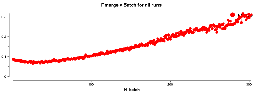 shows the loss in diffraction quality with increasing image number. Of course, this could be due to a variety of reasons (sometimes difficult to assess unless a full 360 degree of data was collected):